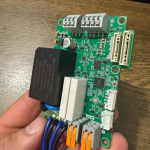
In this design, I’ve implemented power supply using 2s1p LiPo battery pack for Raspberry Pi CM5. It is a kind of UPS design for Raspberry Pi Compute Module. The device was for a handheld imaging gadget for medical usage. The device should operate more than 3 hours with fully charged battery. I designed it to be compatible with both CM4 and CM5. Because Raspberry Pi CM4 didn’t have power on/off button feature, I had to design a custom power on/off button circuit for this board.
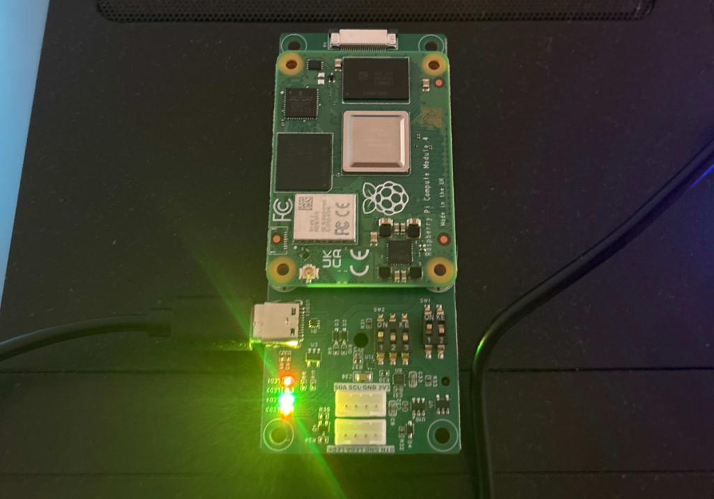
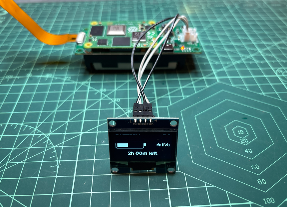
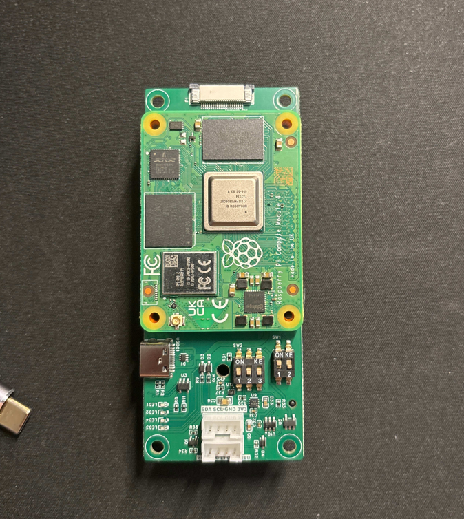
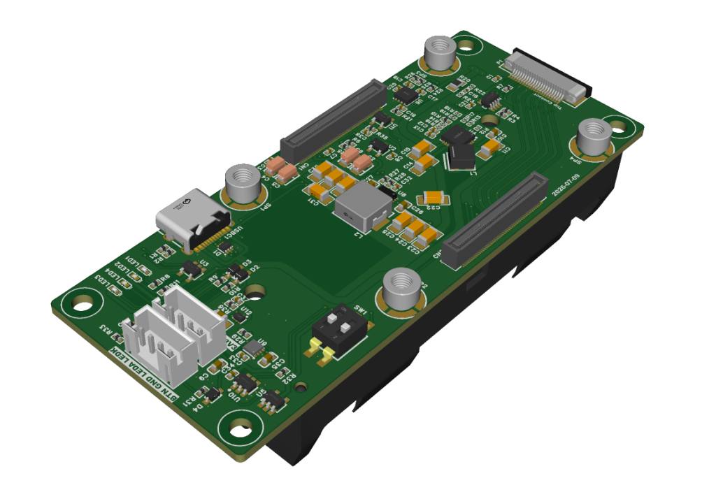
Key Features
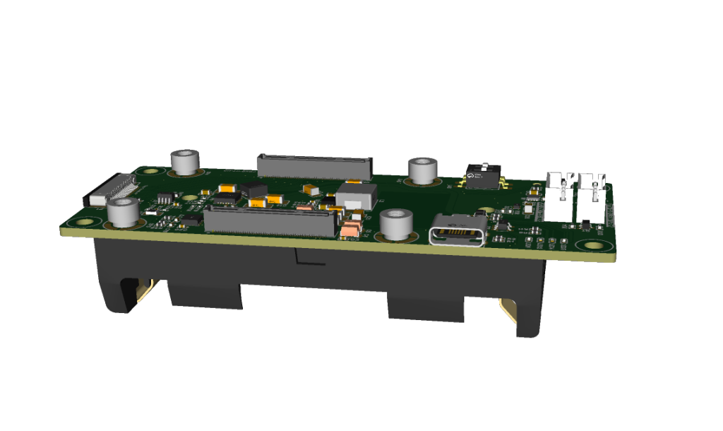
- Raspberry Pi Compute Module connectors: Amphenol 10164227-1004A1RLF
- 1 x MIPI DPHY connector for CSI camera or DSI display
- 1 x USB Type-C port for power supply and charging
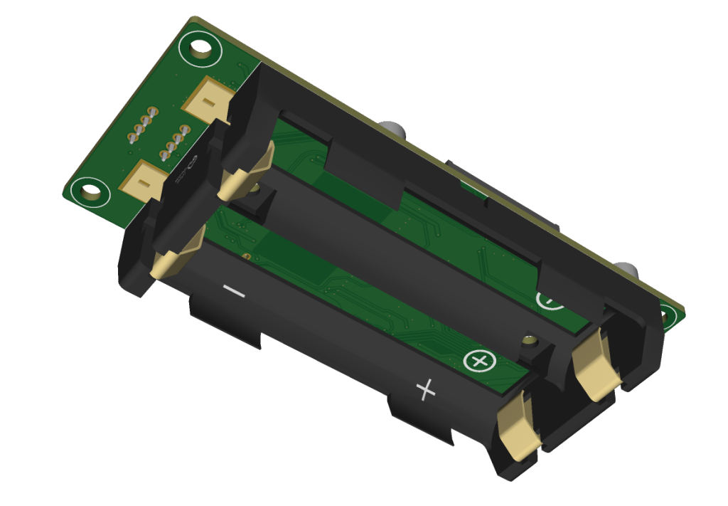
- 2s1p battery holder for 2 x 18650 LiPo cells
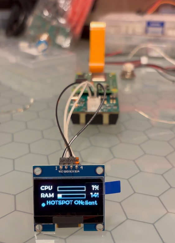
- 2 x JST XH connectors for power button and OLED display installed on enclosure
PCB Design
In this design, there were two main difficulties:
- Circuit design issue of designing custom power on/off button circuit
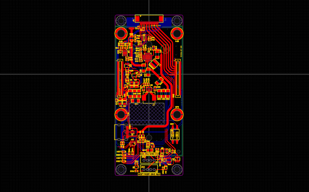
- PCB design issue of putting power supply and battery charger circuit under the compute module
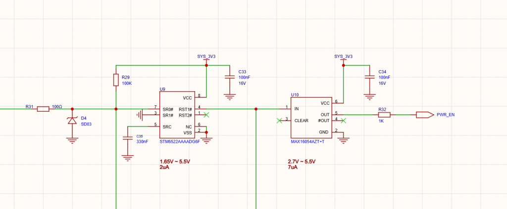
Long-press ON/OFF Power Button Circuit
Although Raspberry Pi CM5 introduced a new power button pin, it’s not suitable for using battery powered devices. The common behavior of power button in these days are supporting both long-press and short click with different features. With the power button of CM5, it’s possible to turn on or off the CM5 itself. But it’s hard to completely cut off the battery from the circuit for reducing off-time power consumption. Moreover, CM4 doesn’t have such power button feature.
I first tried to follow Texas Instruments Application note – “Push Button Circuit” of implementing power button circuit on some of my previous designs. With several buggy iterations, I could finally get it working. However it still did not look like neat to me. I ended up designing it myself. And the outcome was good. The on/off behavior worked exactly as needed.
Switching Power Supplies between CM4/CM5 and the PCB
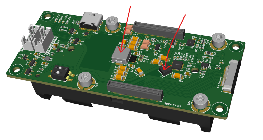
For the UPS like functioning power supply for Raspberry Pi CM4/CM5, my solution was to use two big switching power supply sections.
The first big part was Texas Instruments BQ25886, which requires ~1uH inductor with big enough saturation current rating. The second big part was TPS63070, also from Texas Instruments, a buck-boost converter, that requires 1.5uH with big enough saturation current rating.
I could find 1.9mm tall and 2.3mm tall inductors with the enough inductance and current rating. Before I used Hirose’s 100p mezzanine connectors, but the maximum available height was 3.0mm. With it , I could have only ~1.5mm space under the CM5 compute module. According to the datasheet o Raspberry Pi CM5, the Amphenol 10164227-1004A1RLF is 4.0mm tall connector. With this connector, I could have ~2.5mm space between CM5 and the PCB.
PCBA Prototyping and Testing
My client made a few prototype boards using JLCPCB’s online PCBA service. And it worked well as designed. This board was one of only a few boards that worked 100% correctly. My most other designs had several bugs and I had to go through several design-prototyping-testing iterations.