Recently, I had a chance to design a PCB that can accept almost any voltage as the source of power supply. My client said, “I want it working with DC24V, DC48V, AC110V, or AC220V supplied to the input terminal.” In the following, I showed how I designed it and how it performed in the testing.


Approaching
The board was for monitoring voltage and currents passing through a power rotary switch. The users may connect different power source to the input, likely DC24V, AC110V, or whatever that we can imagine from around us. And the current capacity would be up to 20A.
My client wanted a board that can show the voltage and currents on input and output terminals. And the power supply of microcontroller and display should be taken from the applied input voltage.
I knew that there will be a lot ICs and solutions for 85V~265V AC (which is equivalent to 120 ~ 380V DC) to lower DC voltage regulators, but I was unsure if there were any solution that can accept DC24V ~ DC380V wide range input.
And as always I do, I started googling. It didn’t appear quickly, but it took quite some time that I could finally see a short answer about VIPER01 on a Reddit thread. It was ST Micro’s VIPer family. (I am trying to include the original Reddit thread link here, but I cannot find it again…)
I used ST’s online design tool and it gave nice design and simulation results.
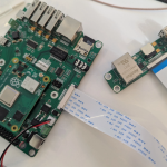
PCB Design, Prototyping, and Testing
Designing the PCB was the same as most of my other ESP32 PCB designs. But there were one irregular part – USB isolation. The circuit that I picked for VIPer01 power supply was non-isolated one. Thus, the board’s ground is electrically connected to one of the power input terminals. It may be one of the AC220V or 380V line in the worst case. Hence, I could not connect USB directly to ESP32 with same ground.
According to the datasheet, VIPer01 series can work with up to 400V AC input, as its maximum rated input voltage was 800V DC. But what about the lowest input supply voltage for operation?
To my surprise, the testing result showed that it started working from DC14V input voltage. I added the diode bridge on the input, thus, there would be 1~2V of voltage drop. So, it means that VIPer013 circuit was outputting regulated 5V correctly from 12V DC input.
And of course, it worked well with all possible voltages we could try – 24V DC, 48V DC, 110V AC, and 220V AC.
The use of diode bridge on the input is mandatory, because we aim this device to be usable for both AC and DC. Thus, the 1~2V voltage drop is consequence. It would be great if our board could accept DC12V source, too. But for now, it is accepting input voltage from 14V DC ~ 550V DC or 10V AC ~ 380V AC, and outputting regulated 5V 200mA.
The ESP32 and OLED display was working fine as expected. But to make this device actually usable, we may need to protect the display and board well from human touch, because we’re using non-isolated power supply.

I thought it’s worth to post about my this experience, because it took me some time to find such solution, and there was no much public resources with proven testing result.
Thank you for reading.

To solve your voltage drop issue, is there a chance something similar to a LT4322 would work? I haven’t dug into some data sheets, but that’s what came to mind.
Yes. such ideal diode-based rectifier is definitely helpful.
LT4322 was also in my radar when I was designing the board.
However, it was pricy – ~$4 per one LT4322, and I needed total 3 rectifiers in my design.
That would increase the BOM cost too much.
And the requirement of input voltage range was for minimum DC24V.
Hence, I did not use it.
Hotte
please get in touch with you email and i will send you datasheets for a project we need doing.
Mark,
You can contact me on Fiverr.