Designing switching power supply is not much difficult these days. We can get a good design using online design tools like TI Webench. For small-power circuits, it mostly work well. However, when it comes to bigger power capacity, it is not very easy.
I started this board design from Jan 2025, and it took almost one year to get the 100% working design. My client spent a lot of time nad funds to rebuild the prototypes and testing it in the field. I truly appreciate him for his effort, patience, and believing in me.
Key Features
- Power Input
- DC 12V nominal from automobile power rails
- 7V ~ 15V input voltage range
- should work at ~7V low input voltage when the engine is starting
- 400W net input power
- DC 12V Aux Backup Battery
- 12V 7Ah Lead-Acid battery
- DC 12V nominal from automobile power rails
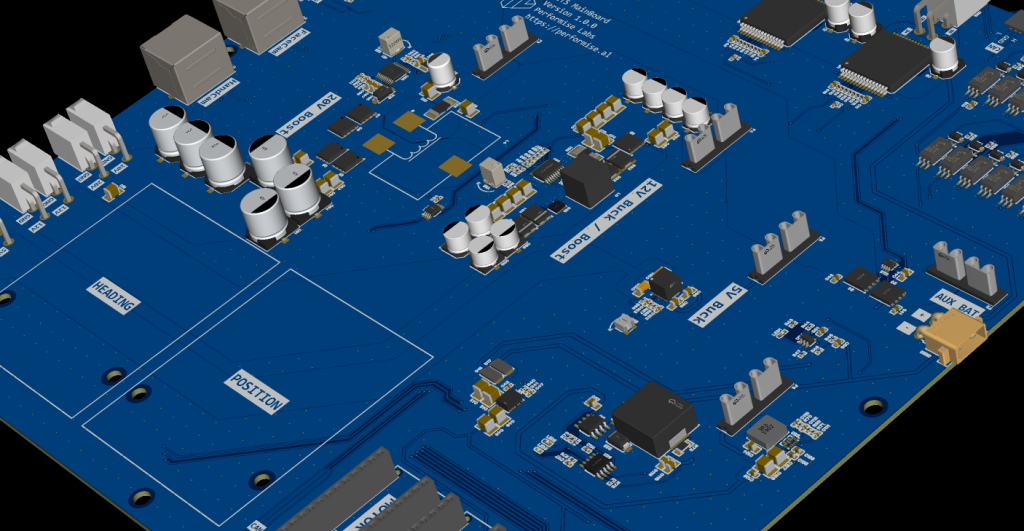
- Power output
- Boost Converter
- Texas Instruments LM5122-Q1
- 24V 8A output
- Buck-Boost Converter
- Texas Instruments LM25118
- 12V 10A output
- Buck Converter
- Texas Instruments TPSM86638
- 5V 6A output
- Boost Converter
- 800mA Lead-Acid battery charger
- Texas Instruments TPS61288 for 16V boost converter
- Consonance CN3863 multi-chemistry battery charger
- Motor Driver
- ST Micro VNH5019
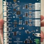
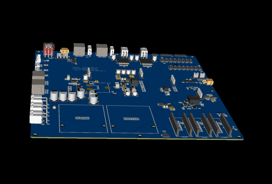
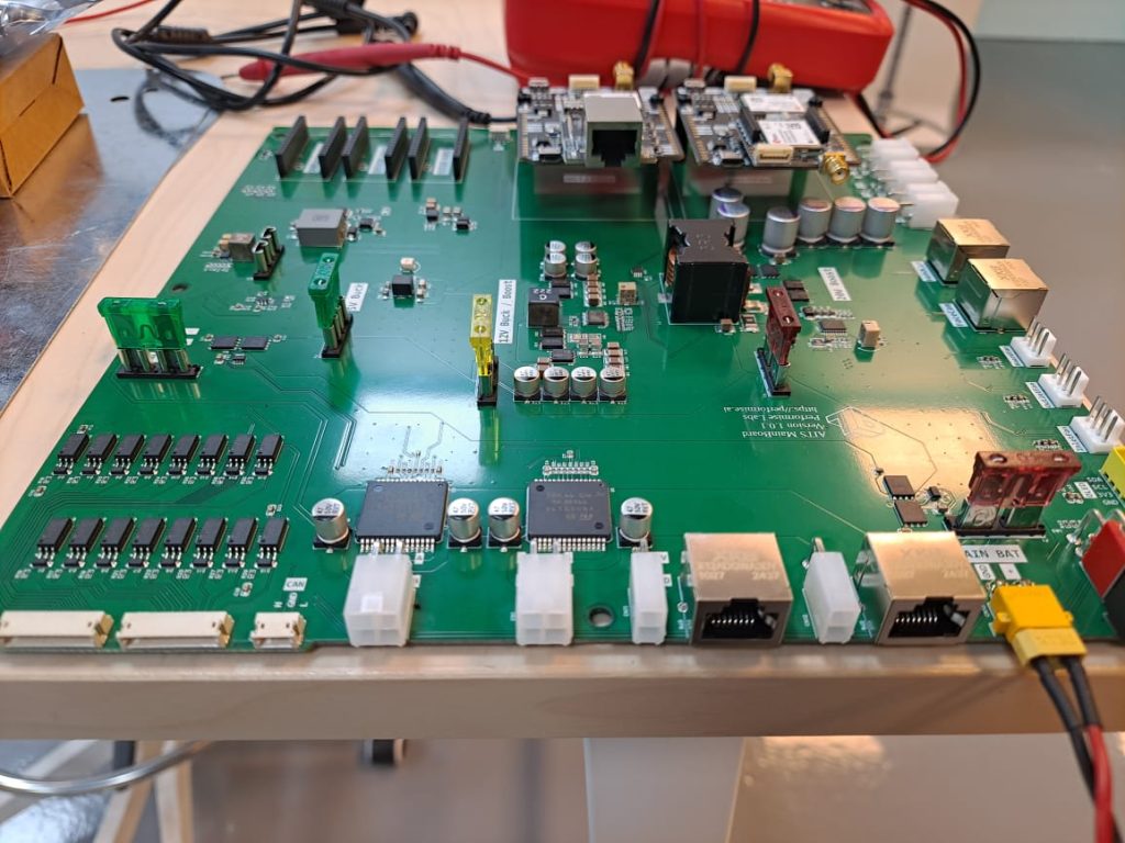
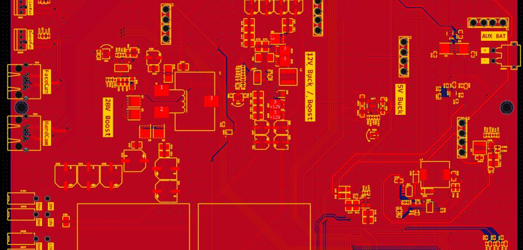
PCB Design
As alwyas, I used EasyEDA Pro for this board design. When the maximum loads are connected, the board’s net power delivery amount is ~350W. Considering the efficiency of switching power supplies are 90~93%, 30W or more amount of power is transformed to heat. Thus, I had to design the heat flux on PCB copper planes carefully.
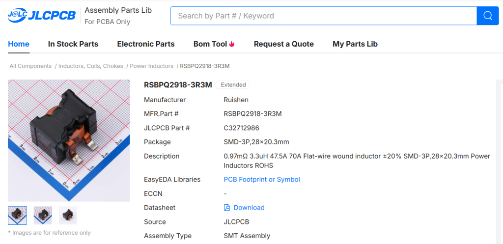
Choosing the inductors were also difficult. At this high power DC-DC converting condition, TI Webench gave custom inductor specs with very low DC resistance and very high saturation current. For example, for 24V boost converter, I could finally find a bulky inductor, which has 0.97mΩ DC resistance and 47.5A 70A saturation current.
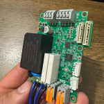
PCBA Prototyping
My client used JLCPCB for making prototypes of all versions. The components were big enough and the they are distributed on a big board for heat dissipation, there was no special issue or bug in assembly process.
For better heat conduction, we tried to use 2mm thickness FR4 board with 2oz copper. But it was nto still enough for heat dissipation. We ended up attaching a custom built aluminum heatsink on the whole bottom surface of PCB. Fortunately, the board size was big enough, and I could place all components on top side only. Hence, the bottom of the board were completely flat and we could find aluminum heatsink easily.